 Q. No.
A student has three \(6.0~\Omega\) resistors that can be connected together in any configuration. What are the maximum and minimum resistance that can be obtained by using one or more of these three resistors?
(Assume the connections between the resistors have negligible resistance, the temperature of the resistors is constant, and the resistors are used in a d.c. circuit and none of the resistors are shortcircuited.)
| 1. | maximum resistance: \(12~\Omega\); minimum resistance: \(0.50~\Omega\) |
| 2. | maximum resistance: \(6.0~\Omega\); minimum resistance: \(0.50~\Omega\) |
| 3. | maximum resistance: \(18~\Omega\); minimum resistance: \(6.0~\Omega\) |
| 4. | maximum resistance: \(18~\Omega\); minimum resistance: \(2.0~\Omega\) |


1. \(7/5\)
2. \(3/5\)
3. \(5/3\)
4. \(6/5\)
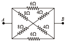
The equivalent resistance between \(A\) and \(B\) for the mesh shown in the figure is:

| 1. | \(7.2\) \(\Omega\) | 2. | \(16\) \(\Omega\) |
| 3. | \(30\) \(\Omega\) | 4. | \(4.8\) \(\Omega\) |


The circuit shown contains three identical resistors, two ammeters X and Y, and a voltmeter Z. The internal resistance of the battery is negligible.
Which option shows the readings on the three meters?
(Assume the ammeters have negligible resistance, and negligible current flows through the voltmeter.)

| 1. | X = \(1.0\) A; Y = \(0.0\) A; Z = \(12\) V |
| 2. | X = \(2.0\) A; Y = \(0.0\) A; Z = \(4.0\) V |
| 3. | X = \(1.0\) A; Y = \(2.0\) A; Z = \(8.0\) V |
| 4. | X = \(3.0\) A; Y = \(6.0\) A; Z = \(12\) V |
The equivalent resistance between points A and B in the circuit shown in the figure is:

1. 6R
2. 4R
3. 2R
4. R
What is the equivalent resistance between A and B in the figure below if R = 3 ?
1. 9

2. 12
3. 15
4. None of these
A potential divider is used to give outputs of 2 V and 3 V from a 5 V source, as shown in the figure.

Which combination of resistances, from the ones given below, give the correct voltages?
| 1. | \(\mathrm{R}_1=1 \mathrm{k} \Omega, \mathrm{R}_2=1 \mathrm{k} \Omega, \mathrm{R}_3=2 \mathrm{k} \Omega\) |
| 2. | \(\mathrm{R}_1=2 \mathrm{k} \Omega, \mathrm{R}_2=1 \mathrm{k} \Omega, \mathrm{R}_3=2 \mathrm{k} \Omega\) |
| 3. | \(\mathrm{R}_1=1 \mathrm{k} \Omega, \mathrm{R}_2=2 \mathrm{k} \Omega, \mathrm{R}_3=2 \mathrm{k} \Omega\) |
| 4. | \(\mathrm{R}_1=3 \mathrm{k} \Omega, \mathrm{R}_2=2 \mathrm{k} \Omega, \mathrm{R}_3=2 \mathrm{k} \Omega\) |
In the circuit shown in the figure, the effective resistance between A and B is:
1. 2
2. 4
3. 6
4. 8
The effective resistance between points P and Q of the electrical circuit shown in the figure is:

1.
2.
3.
4.

1. 10 \(\Omega\)
2. 20 \(\Omega\)
3. 30 \(\Omega\)
4. 40 \(\Omega\)
© 2024 GoodEd Technologies Pvt. Ltd.