
If in a \(\mathrm{p\text-n}\) junction, a square input signal of \(10\) V is applied as shown, then the output across \(R_L\) will be:

| 1. |  |
2. |  |
| 3. |  |
4. |  |


The electrical circuit used to get smooth output from a rectifier circuit is called:
1. oscillator.
2. filter.
3. amplifier.
4. logic gates.
Function of rectifier is
(1) To convert ac into dc
(2) To convert dc into ac
(3) Both (a) and (b)
(4) None of these


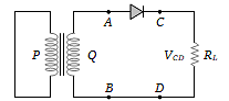
In the diagram, the input is across terminals A and C and the output is across terminals B and D, then the output is:
(1) Zero

(2) Same as input
(3) Full wave rectifier
(4) Half wave rectifier
In the half-wave rectifier circuit shown. Which one of the following wave forms is true for , the output across C and D?
| 1. | 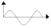 |
2. | 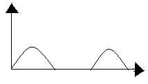 |
| 3. | 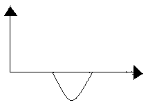 |
4. |  |
A full-wave rectifier circuit along with the input and output voltages is shown in the figure.

The contribution to the output voltage from diode – 2 is :
(1) A, C
(2) B, D
(3) B, C
(4) A, D


The peak voltage in the output of a half-wave diode rectifier fed with a sinusoidal signal without filter is 10 V. The dc component of the output voltage is
(1) V
(2) V
(3) 10 V
(4) V
In a half-wave rectification, what is the output frequency if the input frequency is \(50~\text{Hz}?\)
1. \(50~\text{Hz}\)
2. \(100~\text{Hz}\)
3. \(25~\text{Hz}\)
4. \(60~\text{Hz}\)
| 1. | \(120\) Hz | 2. | zero |
| 3. | \(30\) Hz | 4. | \(60\) Hz |


The circuit represents a full wave bridge rectifier when switch \(S\) is open. The output voltage \((V_0)\) pattern across \(R_L\) when \(S\) is closed:

| 1. |  |
2. |  |
| 3. |  |
4. |  |
© 2026 GoodEd Technologies Pvt. Ltd.