The resistances of the four arms P, Q,R and S in a Wheatstone's bridge are 10Ω ,30Ω ,30Ω and 90Ω, respectively. The emf and internal resistance of the cell are 7 V and 5 Ω respectively. If the galvanometer resistance is 50Ω, the current drawn from the cell will be

(1) 1.0A

(2) 0.2A

(3) 0.1A

(4) 2.0A


Subtopic:  Wheatstone Bridge |
 79%
Level 2: 60%+
NEET - 2013
Hints

A battery of internal resistance \(r\), when connected across \(2~\Omega\) resistor supplies a current of \(4~\text{A}\). When the battery is connected across a \(5~\Omega\) resistor, it supplies a current of \(2~\text{A}\). The value of \(r\) is: 
1. \(2~\Omega\) 2 \(1~\Omega\)
3. \(0.5~\Omega\) 4. zero
Subtopic:  EMF & Terminal Voltage |
 84%
Level 1: 80%+
Hints
Links

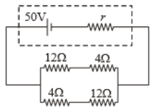
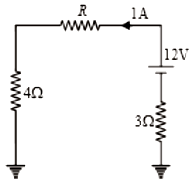
In the circuit shown in figure find the value of r(internal resistance of the cell) for which power transferred by the cell is maximum


1.  4Ω  

2.  12Ω  

3.  16Ω 

4.   8Ω

Subtopic:  Combination of Resistors |
 71%
Level 2: 60%+
Hints

advertisementadvertisement

In the circuit shown in the figure below, the current supplied by the battery is:
 
1. \(2~\text A\) 
2. \(1~\text A\) 
3. \(0.5~\text A\) 
4. \(0.4~\text A\) 

Subtopic:  Wheatstone Bridge |
 89%
Level 1: 80%+
Hints
Links

If a resistance coil is made by joining in parallel two resistances each of 20Ω. An emf of 2V is applied across this coil for 100 seconds. The heat produced in the coil is

(1) 20 J

(2) 10 J

(3) 40 J

(4) 80 J

Subtopic:  Heating Effects of Current |
 79%
Level 2: 60%+
Hints

TwobattriesofemfE1,E2andinternalresistancer1,r2areconnectedinparallel.
TheeffectiveemfofthecircuitacrossAandBis

1.  E1r1+E2r2r1+r2

2.  E1r2+E2r1r1+r2

3.  E1r2+E2r1r1×r2

4.  E1r1+E2r2r1-r2

Subtopic:  Grouping of Cells |
 78%
Level 2: 60%+
Hints

advertisementadvertisement

The equivalent resistance across AB is :


1.  2R

2.  R/2

3.  4R/3

4.  3R/2

Subtopic:  Combination of Resistors |
 76%
Level 2: 60%+
Hints

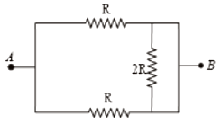
The equivalent resistance between points \(A\) and \(B\) in the circuit shown in the figure is:

1. \(6R\) 2. \(4R\)
3. \(2R\) 4. \(R\)
Subtopic:  Combination of Resistors |
 83%
Level 1: 80%+
Hints
Links

In the circuit shown in the figure, the effective resistance between A and B is:
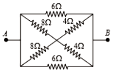
                            

1.  2Ω

2.  4Ω

3.  6Ω

4.  8Ω

Subtopic:  Combination of Resistors |
 81%
Level 1: 80%+
Hints

advertisementadvertisement

For the circuit shown in the figure, the value of R must be


1.  3Ω

2.  4Ω

3.  5Ω

4.  6Ω

Subtopic:  Kirchoff's Voltage Law |
 81%
Level 1: 80%+
Hints