In the LCR series A.C. circuit, as we vary the frequency of A.C. source, peak current is obtained. The value of this peak current, apart from the supply voltage, depends upon (symbols have their usual meaning)
1. L and R
2. L and C
3. R and C
4. R only
The inductive reactance and resistance of the L-R circuit are respectively 30 ohm and 40 ohm. The impedance of the circuit is
1. 50 ohm
2. 10 ohm
3. 70 ohm
4. ohm
Voltage across the resistor, inductor and capacitor in series LCR circuit are 20 V, 50 V and 50 V respectively. Peak value of the applied source is
1. 20 V
2. 20 V
3. 120 V
4. 120 V
The r.m.s value of current for
1. 5 A
2. 5 A
3.
4.
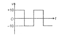
The r.m.s. voltage of the waveform shown is:

1. 10 V
2. 6.37 V
3. 7 V
4. 10.5 v
| 1. | \(10~\text{mA}\) | 2. | \(20~\text{mA}\) |
| 3. | \(40~\text{mA}\) | 4. | \(80~\text{mA}\) |
Voltage and current in an A.C. circuit is given by
Wattful current in the circuit is-
A time-varying current is given by Its r.m.s. value is (symbols have usual meanings)
| 1. | \(V_r=V_L>V_C\) |
| 2. | \(V_R \neq V_L=V_C\) |
| 3. | \(V_R \neq V_L \neq V_C\) |
| 4. | \(V_R=V_C \neq V_L\) |
For the circuit shown in figure below, the ammeter reads 1.6 A and ammeter read 0.4 A If is angular frequency and is frequency of ac, then


