Figure 11.1 depicts a schematic view of the arrangement used for the experimental study of the photoelectric effect. It consists of an evacuated glass/quartz tube having a photosensitive plate C and another metal plate A. Monochromatic light from the source S of sufficiently short wavelength passes through the window W and falls on the photosensitive plate C (emitter). A transparent quartz window is sealed on to the glass tube, which permits ultraviolet radiation to pass through it and irradiate the photosensitive plate C. The electrons are emitted by the plate C and are collected by the plate A (collector), by the electric field created by the battery. The battery maintains the potential difference between the plates C and A, that can be varied. The polarity of the plates C and A can be reversed by a commutator. Thus, the plate A can be maintained at a desired positive or negative potential with respect to emitter C. When the collector plate A is positive with respect to the emitter plate C, the electrons are attracted to it. The emission of electrons causes flow of electric current in the circuit. The potential difference between the emitter and collector plates is measured by a voltmeter (V) whereas the resulting photo current flowing in the circuit is measured by a microammeter (µA). The photoelectric current can be increased or decreased by varying the potential of collector plate A with respect to the emitter plate C. The intensity and frequency of the incident light can be varied, as can the potential difference V between the emitter C and the collector A.
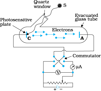
Figure 11.1 Experimental arrangement for study of photoelectric effect.
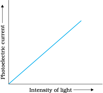
The collector A is maintained at a positive potential with respect to emitter C so that electrons ejected from C are attracted towards collector A. Keeping the frequency of the incident radiation and the potential fixed, the intensity of light is varied and the resulting photoelectric current is measured each time. It is found that the photocurrent increases linearly with intensity of incident light as shown graphically in Fig. 11.2. The photocurrent is directly proportional to the number of photoelectrons emitted per second. This implies that the number of photoelectrons emitted per second is directly proportional to the intensity of incident radiation.
© 2026 GoodEd Technologies Pvt. Ltd.

