Figure 7.8 shows an ac source ε generating ac voltage v = vmsinωt connected to a capacitor only, a purely capacitive ac circuit.
When a capacitor is connected to a voltage source in a dc circuit, current will flow for the short time required to charge the capacitor. As charge accumulates on the capacitor plates, the voltage across them increases, opposing the current. That is, a capacitor in a dc circuit will limit or oppose the current as it charges. When the capacitor is fully charged, the current in the circuit falls to zero.
When the capacitor is connected to an ac source, as in Fig. 7.8, it limits or regulates the current, but does not completely prevent the flow of charge. The capacitor is alternately charged and discharged as the current reverses each half cycle. Let q be the charge on the capacitor at any time t. The instantaneous voltage v across the capacitor is
 (7.15)
From the Kirchhoff’s loop rule, the voltage across the source and the capacitor are equal,
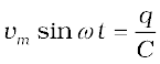
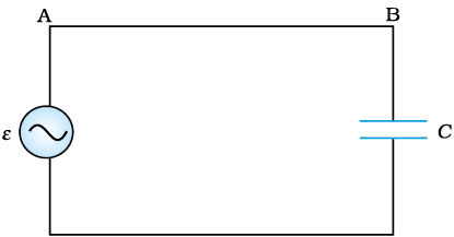
Figure 7.8 An ac source connected to a capacitor.
To find the current, we use the relation 
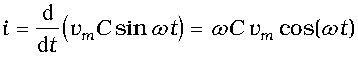
Using the relation, , we have
(7.16)
where the amplitude of the oscillating current is im = (ωC)vm. We can rewrite it as
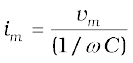
Comparing it to im= vm/R for a purely resistive circuit, we find that (1/ωC) plays the role of resistance. It is called capacitive reactance and is denoted by Xc,
Xc= 1/ωC (7.17)
so that the amplitude of the current is
 (7.18)
The dimension of capacitive reactance is the same as that of resistance and its SI unit is ohm (Ω). The capacitive reactance limits the amplitude of the current in a purely capacitive circuit in the same way as the resistance limits the current in a purely resistive circuit. But it is inversely proportional to the frequency and the capacitance.
A comparison of Eq. (7.16) with the equation of source voltage, Eq. (7.1) shows that the current is π/2 ahead of voltage. 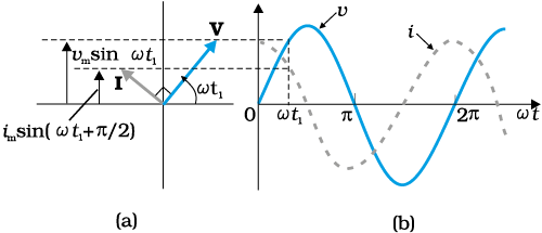
Figure 7.9 (a) A Phasor diagram for the circuit in Fig. 7.8. (b) Graph of v and i versus ωt.
Figure 7.9(a) shows the phasor diagram at an instant t1. Here the current phasor I is π/2 ahead of the voltage phasor V as they rotate counterclockwise. Figure 7.9(b) shows the variation of voltage and current with time. We see that the current reaches its maximum value earlier than the voltage by one-fourth of a period.
The instantaneous power supplied to the capacitor is
pc = i v = im cos(ωt)vm sin(ωt)
= im vm cos(ωt) sin(ωt)
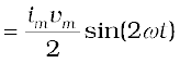 (7.19)
So, as in the case of an inductor, the average power
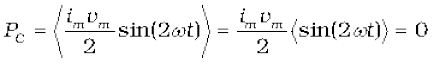
since ωt)> = 0 over a complete cycle. Figure 7.10 explains it in detail.
Thus, we see that in the case of an inductor, the current lags the voltage by π/2 and in the case of a capacitor, the current leads the voltage by π/2.
Example 7.3 A lamp is connected in series with a capacitor. Predict your observations for dc and ac connections. What happens in each case if the capacitance of the capacitor is reduced?
Solution When a dc source is connected to a capacitor, the capacitor gets charged and after charging no current flows in the circuit and the lamp will not glow. There will be no change even if C is reduced. With ac source, the capacitor offers capacitative reactance (1/ωC) and the current flows in the circuit. Consequently, the lamp will shine. Reducing C will increase reactance and the lamp will shine less brightly than before.
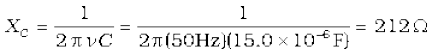
Example 7.4 A 15.0 µF capacitor is connected to a 220 V, 50 Hz source. Find the capacitive reactance and the current (rms and peak) in the circuit. If the frequency is doubled, what happens to the capacitive reactance and the current?
Solution The capacitive reactance is
The rms current is
The peak current is
This current oscillates between +1.47A and –1.47 A, and is ahead of the voltage by π/2.
If the frequency is doubled, the capacitive reactance is halved and consequently, the current is doubled.
Example 7.5 A light bulb and an open coil inductor are connected to an ac source through a key as shown in Fig. 7.11.
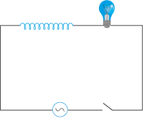
Figure 7.11
The switch is closed and after sometime, an iron rod is inserted into the interior of the inductor. The glow of the light bulb (a) increases; (b) decreases; (c) is unchanged, as the iron rod is inserted. Give your answer with reasons.
Solution As the iron rod is inserted, the magnetic field inside the coil magnetizes the iron increasing the magnetic field inside it. Hence, the inductance of the coil increases. Consequently, the inductive reactance of the coil increases. As a result, a larger fraction of the applied ac voltage appears across the inductor, leaving less voltage across the bulb. Therefore, the glow of the light bulb decreases.
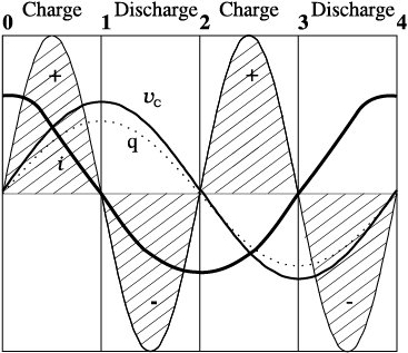
One complete cycle of voltage/current. Note that the current leads the voltage.
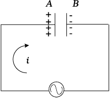
0-1 The current i flows as shown and from the maximum at 0, reaches a zero value at 1. The plate A is charged to positive polarity while negative charge q builds up in B reaching a maximum at 1 until the current becomes zero. The voltage vc = q/C is in phase with q and reaches maximum value at 1. Current and voltage are both positive. So p = vci is positive.
Energy is absorbed from THE SOURCE during this quarter cycle AS THE CAPACITOR IS CHARGED.
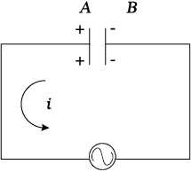
1-2 The current i reverses its direction. The accumulated charge is depleted i.e., the capacitor is discharged during this quarter cycle.The voltage gets reduced but is still positive. The current is negative. Their product, the power is negative.
the Energy absorbed during THE 1/4 CYCLE 0-1 IS RETURNED DURING this QUARTER.
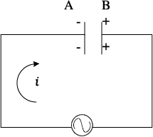
2-3 As i continues to flow from A to B, the capacitor is charged to reversed polarity i.e., the plate B acquires positive and A acquires negative charge. Both the current and the voltage are negative. Their product p is positive. The capacitor ABSORBS ENERGY during this 1/4 cycle.
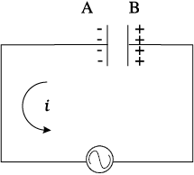
3-4 The current i reverses its direction at 3 and flows from B to A. The accumulated charge is depleted and the magnitude of the voltage vc is reduced. vc becomes zero at 4 when the capacitor is fully discharged. The power is negative.ENERGY ABSORBED DURING 2-3 IS RETURNED TO THE SOURCE. NET ENERGY ABSORBED IS ZERO.
Figure 7.10 Charging and discharging of a capacitor.
© 2026 GoodEd Technologies Pvt. Ltd.

