In the previous chapter, we have explained how a current loop acts as a magnetic dipole (Section 4.10). We mentioned Ampere’s hypothesis that all magnetic phenomena can be explained in terms of circulating currents. Recall that the magnetic dipole moment m associated with a current loop was defined to be m = NIA where N is the number of turns in the loop, I the current and A the area vector (Eq. 4.30).
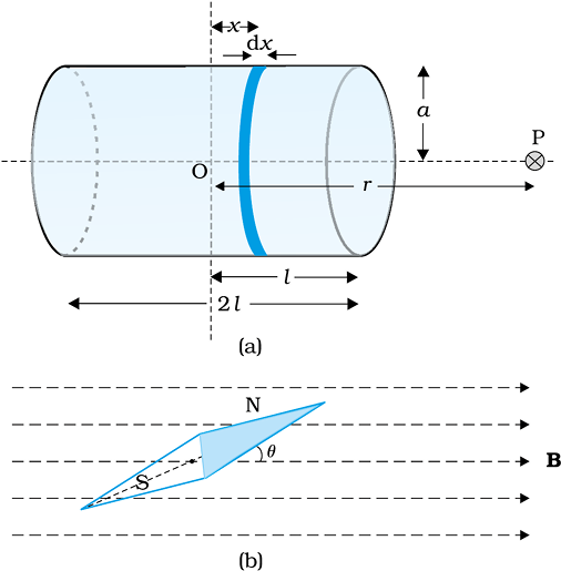
Figure 5.4 Calculation of (a) The axial field of a finite solenoid in order to demonstrate its similarity to that of a bar magnet. (b) A magnetic needle in a uniform magnetic field B. The arrangement may be used to determine either B or the magnetic moment m of the needle.
The resemblance of magnetic field lines for a bar magnet and a solenoid suggest that a bar magnet may be thought of as a large number of circulating currents in analogy with a solenoid. Cutting a bar magnet in half is like cutting a solenoid. We get two smaller solenoids with weaker magnetic properties. The field lines remain continuous, emerging from one face of the solenoid and entering into the other face. One can test this analogy by moving a small compass needle in the neighbourhood of a bar magnet and a current-carrying finite solenoid and noting that the deflections of the needle are similar in both cases.
To make this analogy more firm we calculate the axial field of a finite solenoid depicted in Fig. 5.4 (a). We shall demonstrate that at large distances this axial field resembles that of a bar magnet.
Let the solenoid of Fig. 5.4(a) consists of n turns per unit length. Let its length be 2l and radius a. We can evaluate the axial field at a point P, at a distance r from the centre O of the solenoid. To do this, consider a circular element of thickness dx of the solenoid at a distance x from its centre. It consists of n dx turns. Let I be the current in the solenoid. In Section 4.6 of the previous chapter we have calculated the magnetic field on the axis of a circular current loop. From Eq. (4.13), the magnitude of the field at point P due to the circular element is
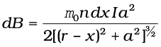
The magnitude of the total field is obtained by summing over all the elements — in other words by integrating from x = – l to x = + l. Thus,
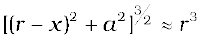
This integration can be done by trigonometric substitutions. This exercise, however, is not necessary for our purpose. Note that the range of x is from – l to + l. Consider the far axial field of the solenoid, i.e.,
r >> a and r >> l. Then the denominator is approximated by
and
= (5.1)
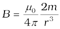
Note that the magnitude of the magnetic moment of the solenoid is, m = n (2l) I (πa2) — (total number of turns × current × cross-sectional area). Thus,
 (5.2)
(5.2)
This is also the far axial magnetic field of a bar magnet which one may obtain experimentally. Thus, a bar magnet and a solenoid produce similar magnetic fields. The magnetic moment of a bar magnet is thus equal to the magnetic moment of an equivalent solenoid that produces the same magnetic field.
Some textbooks assign a magnetic charge (also called pole strength) +qm to the north pole and –qm to the south pole of a bar magnet of length 2l, and magnetic moment qm (2l). The field strength due to qm at a distance r from it is given by µ0qm /4πr2. The magnetic field due to the bar magnet is then obtained, both for the axial and the equatorial case, in a manner analogous to that of an electric dipole (Chapter 1). The method is simple and appealing. However, magnetic monopoles do not exist, and we have avoided this approach for that reason.
© 2026 GoodEd Technologies Pvt. Ltd.

