14.16 Write the truth table for a NAND gate connected as given in Fig. 14.37.

Figure 14.37
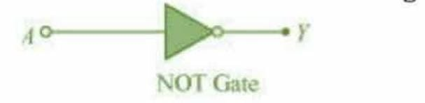
Hence identify the exact logic operation carried out by this circuit.
A act as the two inputs of the NAND and Y is the output, as shown in the following figure.
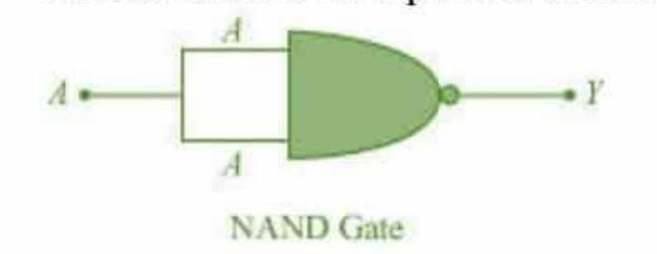
Hence, the output can be written as:
The truth table for equation (i) can be drawn as:
|
A |
Y=(A) |
|
0 |
1 |
|
1 |
0 |
© 2026 GoodEd Technologies Pvt. Ltd.

