 Q. No.
If there are two bulbs of \((40~\text{W},200~\text{V}),\) and \((100~\text{W},200~\text{V}),\) then the correct relation for their resistance is:
1. \(R_{40}<R_{100}\)
2. \(R_{40}>R_{100}\)
3. \(R_{40}=R_{100}\)
4. no relation can be predicted


A \(5~\text A\) fuse wire can withstand a maximum power of \(1~\text W\) in a circuit. The resistance of the fuse wire is:
1. \(5~\Omega\)
2. \(0.04~\Omega\)
3. \(0.2~\Omega\)
4. \(0.4~\Omega\)
The total power dissipated in watts in the circuit shown below is:


| 1. | \(16\) W | 2. | \(40\) W |
| 3. | \(54\) W | 4. | \(4\) W |


Two cities are \(150~\text{km}\) apart. The electric power is sent from one city to another city through copper wires. The fall of potential per km is \(8~\text{volts}\) and the average resistance per \(\text{km}\) is \(0.5~\text{ohm}.\) The power loss in the wire is:
1. \(19.2~\text{W}\)
2. \(19.2~\text{kW}\)
3. \(19.2~\text{J}\)
4. \(12.2~\text{kW}\)
A current of \(3~\text{A}\) flows through the \(2~\Omega\) resistor shown in the circuit. The power dissipated in the \(5~\Omega\) resistor is:

| 1. | \(4~\text{W}\) | 2. | \(2~\text{W}\) |
| 3. | \(1~\text{W}\) | 4. | \(5~\text{W}\) |
If power dissipated in the \(9~\Omega\) resistor in the circuit shown is \(36\) W, the potential difference across the \(2~\Omega\) resistor will be:

1. \(8\) V
2. \(10\) V
3. \(2\) V
4. \(4\) V


If the voltage across a bulb rated \((220~\text{V}\text-100~\text{W})\) drops by \(2.5\%\) of its rated value, the percentage of the rated value by which the power would decrease is:
1. \(20\%\)
2. \(2.5\%\)
3. \(5\%\)
4. \(10\%\)
When three identical bulbs are connected in series, the consumed power is \(10\) W. If they are now connected in parallel then the consumed power will be:
1. \(30\) W
2. \(90\) W
3. \(\frac{10}{3}\) W
4. \(270\) W
Power consumed in the given circuit is \(P_1.\) On interchanging the position of \(3~\Omega\) and \(12~\Omega\) resistances, the new power consumption is \(P_2.\) The ratio of \(\dfrac{P_2}{P_1}\) is:
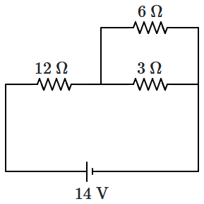
| 1. | \(2\) | 2. | \(\dfrac 12\) |
| 3. | \(\dfrac 35\) | 4. | \(\dfrac 25\) |


The power dissipated across the \(8~\Omega\) resistor in the circuit shown here is \(2~\text{W}\). The power dissipated in watts across the \(3~\Omega\) resistor is:

| 1. | \(2.0\) | 2. | \(1.0\) |
| 3. | \(0.5\) | 4. | \(3.0\) |
© 2025 GoodEd Technologies Pvt. Ltd.