
 Q. No.
A potential divider is used to give outputs of \(2~\text{V}\) and \(3~\text{V}\) from a \(5~\text{V}\) source, as shown in the figure.

Which combination of resistances, from the ones given below, \(R_1, R_2, ~\text{and}~R_3\) give the correct voltages?
1.
\({R}_1=1~\text{k} \Omega, {R}_2=1 ~\text{k} \Omega, {R}_3=2 ~\text{k} \Omega\)
2.
\({R}_1=2 ~\text{k} \Omega, {R}_2=1~\text{k} \Omega, {R}_3=2~\text{k} \Omega\)
3.
\({R}_1=1 ~\text{k} \Omega, {R}_2=2~ \text{k} \Omega, {R}_3=2~ \text{k} \Omega\)
4.
\({R}_1=3~\text{k} \Omega, {R}_2=2~\text{k} \Omega, {R}_3=2~ \text{k} \Omega\)


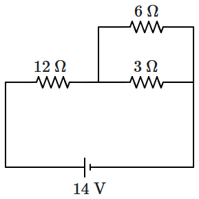
For the given circuit, the value of the resistance in which the maximum heat is produced is:
1. \(2~\Omega\)
2. \(6~\Omega\)
3. \(4~\Omega\)
4. \(12~\Omega\)

A charged particle having drift velocity of \(7.5\times10^{-4}~\text{ms}^{-1}\) in an electric field of \(3\times10^{-10}~\text{Vm}^{-1},\) has mobility of:
1. \(2.5\times 10^{6}~\text{m}^2\text{V}^{-1}\text{s}^{-1}\)
2. \(2.5\times 10^{-6}~\text{m}^2\text{V}^{-1}\text{s}^{-1}\)
3. \(2.25\times 10^{-15}~\text{m}^2\text{V}^{-1}\text{s}^{-1}\)
4. \(2.25\times 10^{15}~\text{m}^2\text{V}^{-1}\text{s}^{-1}\)


Two batteries, one of emf \(18~\text{V}\) and internal resistance \(2~\Omega\) and the other of emf \(12~\text V\) and internal resistance \(1~\Omega,\) are connected as shown. Reading of the voltmeter is:
(if a voltmeter is ideal)

1. \(14~\text V\)
2. \(15~\text V\)
3. \(18~\text V\)
4. \(30~\text V\)
Current through the \(2~\Omega\) resistance in the electrical network shown is:

| 1. | zero | 2. | \(1~\text A\) |
| 3. | \(3~\text A\) | 4. | \(5~\text A\) |
The dependence of resistivity \((\rho)\) on the temperature \((T)\) of a semiconductor is, roughly, represented by:
| 1. |  |
2. |  |
| 3. |  |
4. |  |


What is the reading of the voltmeter of resistance \(1200~\Omega\) connected in the following circuit diagram?

| 1. | \(2.5\) V | 2. | \(5.0\) V |
| 3. | \(7.5\) V | 4. | \(40\) V |
| 1. | \(10^{\circ}\text{C}\) | 2. | \(5^{\circ}\text{C}\) |
| 3. | \(20^{\circ}\text{C}\) | 4. | \(15^{\circ}\text{C}\) |
Power consumed in the given circuit is \(P_1.\) On interchanging the position of \(3~\Omega\) and \(12~\Omega\) resistances, the new power consumption is \(P_2.\) The ratio of \(\dfrac{P_2}{P_1}\) is:
| 1. | \(2\) | 2. | \(\dfrac 12\) |
| 3. | \(\dfrac 35\) | 4. | \(\dfrac 25\) |
The figure below shows a network of currents. The current \(i\) will be:

1. \(3~\text{A}\)
2. \(13~\text{A}\)
3. \(23~\text{A}\)
4. \(-3~\text{A}\)
© 2025 GoodEd Technologies Pvt. Ltd.