
 Q. No.
An electric dipole of moment \(\vec {p} \) is lying along a uniform electric field \(\vec{E}\). The work done in rotating the dipole by \(90^{\circ}\) is:
1. \(\sqrt{2}pE\)
2. \(\frac{pE}{2}\)
3. \(2pE\)
4. \(pE\)
1. \(\sqrt{2}pE\)
2. \(\frac{pE}{2}\)
3. \(2pE\)
4. \(pE\)


The electric potential at a point in free space due to a charge \(Q\) coulomb is \(Q\times10^{11}~\text{V}\). The electric field at that point is:
1. \(4\pi \varepsilon_0 Q\times 10^{22}~\text{V/m}\)
2. \(12\pi \varepsilon_0 Q\times 10^{20}~\text{V/m}\)
3. \(4\pi \varepsilon_0 Q\times 10^{20}~\text{V/m}\)
4. \(12\pi \varepsilon_0 Q\times 10^{22}~\text{V/m}\)
Four electric charges \(+\mathrm q,\) \(+\mathrm q,\) \(-\mathrm q\) and \(-\mathrm q\) are placed at the corners of a square of side \(2\mathrm{L}\) (see figure). The electric potential at point A, mid-way between the two charges \(+\mathrm q\) and \(+\mathrm q\) is:

1.
2.
3. zero
4.


The variation of potential with distance x from a fixed point is shown in the figure. The electric field at x =13 m is:

1. 7.5 volt/meter
2. –7.5 volt/meter
3. 5 volt/meter
4. –5 volt/meter
Three uncharged capacitors of capacities \(C_1, C_2~\text{and}~C_3~~\) are connected to one another as shown in the figure.

If points \(\mathrm{A}\), \(\mathrm{B}\), and \(\mathrm{D}\), are at potential \(V_1, V_2 ~\text{and}~V_3\) then the potential at \(\mathrm{O}\) will be:
1. \(\frac{V_1C_1+V_2C_2+V_3C_3}{C_1+C_2+C_3}\)
2. \(\frac{V_1+V_2+V_3}{C_1+C_2+C_3}\)
3. \(\frac{V_1(V_2+V_3)}{C_1(C_2+C_3)}\)
4. \(\frac{V_1V_2V_3}{C_1C_2C_3}\)
The figure shows some of the equipotential surfaces. Magnitude and direction of the electric field is given by:
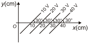
| 1. | 200 V/m, making an angle \(120^\circ\)with the x-axis |
| 2. | 100 V/m, pointing towards the negative x-axis |
| 3. | 200 V/m, making an angle \(60^\circ\)with the x-axis |
| 4. | 100 V/m, making an angle \(30^\circ\)with the x-axis |
In the given figure if , each plate of the capacitor has a surface area of and the plates are apart, then the number of excess electrons on the negative plate is:

1.
2.
3.
4.
Two equal charges q of opposite sign separated by a distance 2a constitute an electric dipole of dipole moment p. If P is a point at a distance r from the centre of the dipole and the line joining the centre of the dipole to this point makes an angle θ with the axis of the dipole, then the potential at P is given by: (r >> 2a) (Where p = 2qa)
| 1. | \(V={pcos \theta \over 4 \pi \varepsilon_0r^2}\) | 2. | \(V={pcos \theta \over 4 \pi \varepsilon_0r}\) |
| 3. | \(V={psin \theta \over 4 \pi \varepsilon_0r}\) | 4. | \(V={pcos \theta \over 2 \pi \varepsilon_0r^2}\) |
Two thin dielectric slabs of dielectric constants K1&K2 () are inserted between plates of a parallel capacitor, as shown in the figure. The variation of electric field E between the plates with distance d as measured from plate P is correctly shown by:

| 1. |  |
2. |  |
| 3. |  |
4. |  |
A conducting sphere of radius R is given a charge Q. The electric potential and field at the center of the sphere respectively are:
| 1. | Zero and \(\mathrm{Q} / 4 \pi \varepsilon_{\mathrm{o}} \mathrm{R}^2\) |
| 2. | \(\mathrm{Q} / 4 \pi \varepsilon_{\mathrm{O}} \mathrm{R}\) and zero |
| 3. | \(\mathrm{Q} / 4 \pi \varepsilon_{\mathrm{O}} \mathrm{R}\) and \(\mathrm{Q} / 4 \pi \varepsilon_{\mathrm{o}} \mathrm{R}^2\) |
| 4. | Both are zero |
© 2024 GoodEd Technologies Pvt. Ltd.