
 Q. No.
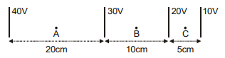
Some equipotential surfaces are shown in figure. The electric field at points A, B and C are respectively:
1.
\(1 \mathrm{~V} / \mathrm{cm}, \frac{1}{2} \mathrm{~V} / \mathrm{cm}, 2 \mathrm{~V} / \mathrm{cm} \text { (all along +ve X-axis) }\)
2.
\(1 \mathrm{~V} / \mathrm{cm}, \frac{1}{2} \mathrm{~V} / \mathrm{cm}, 2 \mathrm{~V} / \mathrm{cm} \text { (all along -ve X-axis) }\)
3.
\(\frac{1}{2} \mathrm{~V} / \mathrm{cm}, 1 \mathrm{~V} / \mathrm{cm}, 2 \mathrm{~V} / \mathrm{cm} \text { (all along +ve X-axis) }\)
4.
\(\frac{1}{2} \mathrm{~V} / \mathrm{cm}, 1 \mathrm{~V} / \mathrm{cm}, 2 \mathrm{~V} / \mathrm{cm} \text { (all along -ve X-axis) }\)


A parallel plate air capacitor is charged to potential difference V. After disconnecting the battery, the distance between the plates of the capacitor is increased using an insulating handle. As a result the potential difference between the plates:
1. decreases.
2. increases.
3. becomes zero.
4. does not change.
A short electric dipole has a dipole moment of \(16 \times 10^{-9} ~\text{C-}\text{m}\). The electric potential due to the dipole at a point at a distance of \(0.6~\text{m}\) from the centre of the dipole situated on a line making an angle of \(60^{\circ}\) with the dipole axis is: \(\left( \frac{1}{4\pi \varepsilon_0}= 9\times 10^{9}~\text{N-m}^2/\text{C}^2\right)\)
1. \(200~\text{V}\)
2. \(400~\text{V}\)
3. zero
4. \(50~\text{V}\)


The increasing order of the electrostatic potential energies for the given system of charges is given by:

| 1. | a = d < b < c | 2. | b = d < c < a |
| 3. | b = c < a < d | 4. | c < a < b < d |
Which of the following statements is correct regarding electrostatics of conductors?
| 1. | The interior of the conductor with no cavity can have no excess charge in the static situation. |
| 2. | Electrostatic potential is constant throughout the volume of the conductor. |
| 3. | Electrostatic potential has the same value inside as that on its surface. |
| 4. | All of these. |
Two capacitors of capacity and are charged to the same potential difference of 6 V. Now they are connected with opposite polarity as shown. After closing switches , their final potential difference becomes:

| 1. | \(\text{Zero} \) | 2. | \(\frac{4}{3} \mathrm{~V} \) |
| 3. | \(3 \mathrm{~V} \) | 4. | \(\frac{6}{5} \mathrm{~V}\) |
The equivalent capacitance across \(A\) and \(B\) in the given figure is:
1. \( \frac{3}{2}C\)
2. \(C\)
3. \( \frac{2}{3}C\)
4. \( \frac{5}{3}C\)
Two concentric metallic spherical shells A and B of radii a and b respectively (b>a) are arranged such that outer shell is earthed and inner shell is charged to Q. Charge on the outer surface of outer shell will be:
1.
2.
3. -Q
4. zero
Two capacitors of capacitance \(6~\mu\text{F}\) and \(3~\mu\text{F}\) are connected in series with battery of \(30~\text{V}\). The charge on \(3~\mu\text{F}\) capacitor at a steady state is:
1. \( 3 ~\mu\text{C}\)
2. \( 1.5 ~\mu\text{C}\)
3. \( 60~\mu\text{C}\)
4. \( 900~\mu\text{C}\)


© 2024 GoodEd Technologies Pvt. Ltd.