
 Q. No.
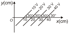
The figure shows some of the equipotential surfaces. Magnitude and direction of the electric field is given by:
1.
200 V/m, making an angle \(120^\circ\)with the x-axis
2.
100 V/m, pointing towards the negative x-axis
3.
200 V/m, making an angle \(60^\circ\)with the x-axis
4.
100 V/m, making an angle \(30^\circ\)with the x-axis


In the given figure if , each plate of the capacitor has a surface area of and the plates are apart, then the number of excess electrons on the negative plate is:

1.
2.
3.
4.
Two equal charges q of opposite sign separated by a distance 2a constitute an electric dipole of dipole moment p. If P is a point at a distance r from the centre of the dipole and the line joining the centre of the dipole to this point makes an angle θ with the axis of the dipole, then the potential at P is given by: (r >> 2a) (Where p = 2qa)
| 1. | \(V={pcos \theta \over 4 \pi \varepsilon_0r^2}\) | 2. | \(V={pcos \theta \over 4 \pi \varepsilon_0r}\) |
| 3. | \(V={psin \theta \over 4 \pi \varepsilon_0r}\) | 4. | \(V={pcos \theta \over 2 \pi \varepsilon_0r^2}\) |


Two thin dielectric slabs of dielectric constants K1&K2 () are inserted between plates of a parallel capacitor, as shown in the figure. The variation of electric field E between the plates with distance d as measured from plate P is correctly shown by:

| 1. |  |
2. |  |
| 3. |  |
4. |  |
A conducting sphere of radius R is given a charge Q. The electric potential and field at the center of the sphere respectively are:
| 1. | Zero and \(\mathrm{Q} / 4 \pi \varepsilon_{\mathrm{o}} \mathrm{R}^2\) |
| 2. | \(\mathrm{Q} / 4 \pi \varepsilon_{\mathrm{O}} \mathrm{R}\) and zero |
| 3. | \(\mathrm{Q} / 4 \pi \varepsilon_{\mathrm{O}} \mathrm{R}\) and \(\mathrm{Q} / 4 \pi \varepsilon_{\mathrm{o}} \mathrm{R}^2\) |
| 4. | Both are zero |
An electric dipole of moment \(p\) is placed in an electric field of intensity \(E\). The dipole acquires a position such that the axis of the dipole makes an angle \(\theta\) with the direction of the field. Assuming that the potential energy of the dipole to be zero when \(\theta = 90^{\circ},\) the torque and the potential energy of the dipole will respectively be:
| 1. | \(p E \sin \theta,-p E \cos \theta\) | 2. | \(p E \sin \theta,-2 p E \cos \theta\) |
| 3. | \(p E \sin \theta, 2 p E \cos \theta\) | 4. | \(p E \cos \theta,-p E \sin \theta\) |

Two capacitors of capacitance \(6~\mu\text{F}\) and \(3~\mu\text{F}\) are connected in series with battery of \(30~\text{V}\). The charge on \(3~\mu\text{F}\) capacitor at a steady state is:
1. \( 3 ~\mu\text{C}\)
2. \( 1.5 ~\mu\text{C}\)
3. \( 60~\mu\text{C}\)
4. \( 900~\mu\text{C}\)

Two concentric metallic spherical shells A and B of radii a and b respectively (b>a) are arranged such that outer shell is earthed and inner shell is charged to Q. Charge on the outer surface of outer shell will be:
1.
2.
3. -Q
4. zero
The equivalent capacitance across \(A\) and \(B\) in the given figure is:
1. \( \frac{3}{2}C\)
2. \(C\)
3. \( \frac{2}{3}C\)
4. \( \frac{5}{3}C\)
© 2024 GoodEd Technologies Pvt. Ltd.