
 Q. No.
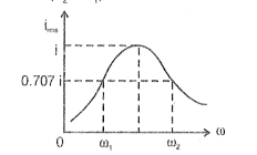
The RMS value of the current in a series LCR circuit is plotted with angular frequency as shown below. The ohmic resistance is R, inductance is L and capacitance is C in the circuit. The value of the difference (is


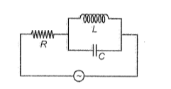
In the circuit diagram shown below, the reading of the \(\mathrm{a.c.}\) voltmeter is
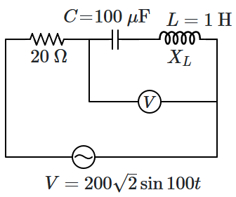
1. \(200\text{ V}\)
2. \(100\text{ V}\)
3. \(50\sqrt2\text{ V}\)
4. zero
In a series RLC alternating current circuit, the r.m.s. value of current is , the average power loss in the circuit is


A step-down transformer transforms 200 V to 100 volts. If the current in primary and secondary coils are 6 A and 9.6 A respectively, the efficiency of the transformer is
1. 60%
2. 70%
3. 80%
4. 90%
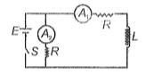
An ideal inductor connected to a cell is shown in figure. Select the correct relations between readings of ammeters just after the switch is closed and a long time after closing the switch
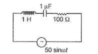
The power dissipated in the following circuit will be about half of its maximum value at approximately


An ac source of emf e=50 sin 100 is connected across a circuit for which the phasor diagram is shown in the figure. The time difference between current and voltage applied across the circuit is
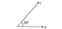
1. 1.25 ms
2. 1.33 ms
3. 1.67 ms
4. 1.85 ms
The instantaneous values of current (in ampere) and potential (in volt) in an A.C. circuit are I= 4 sin and V=100cos respectively. The power factor of the circuit is
In the given A.C. circuit, the instantaneous current through inductor and capacitor are 0.8 A and 0.4 A respectively. The instantaneous current through the resistor is
1. 1.2 A
2. 0.6 a
3. 0.4 A
4. A


In the LCR series A.C. circuit, as we vary the frequency of A.C. source, peak current is obtained. The value of this peak current, apart from the supply voltage, depends upon (symbols have their usual meaning)
1. L and R
2. L and C
3. R and C
4. R only
© 2026 GoodEd Technologies Pvt. Ltd.