The equivalent resistance between \(A\) and \(B\) is:

1. \(3~\Omega\)
2. \(6~\Omega\)
3. \(9~\Omega\)
4. \(12~\Omega\)
The current through the \(5~\Omega\) resistor is:
| 1. | \(3.2~\text A\) | 2. | \(2.8~\text A\) |
| 3. | \(0.8~\text A\) | 4. | \(0.2~\text A\) |
Equivalent resistance across terminals \(A\) and \(B\) will be:
| 1. | \(1~\Omega\) | 2. | \(2~\Omega\) |
| 3. | \(3~\Omega\) | 4. | \(4~\Omega\) |
Consider the circuit shown in the figure below. The current \(I_3\) is equal to:
1. \(5\) A
2. \(3\) A
3. \(-3\) A
4. \(\frac{-5}{6}\) A
The effective resistance between points \(P\) and \(Q\) of the electrical circuit shown in the figure is:

| 1. | \(\frac{2 R r}{\left(R + r \right)}\) | 2. | \(\frac{8R\left(R + r\right)}{\left( 3 R + r\right)}\) |
| 3. | \(2r+4R\) | 4. | \(\frac{5R}{2}+2r\) |
The resistance of a wire is \(R\) ohm. If it is melted and stretched to \(n\) times its original length, its new resistance will be:
| 1. | \(nR\) | 2. | \(\frac{R}{n}\) |
| 3. | \(n^2R\) | 4. | \(\frac{R}{n^2}\) |
Two metal wires of identical dimensions are connected in series. If \(\sigma_1~\text{and}~\sigma_2\)
1. \(\dfrac{2\sigma_1 \sigma_2}{\sigma_1+\sigma_2}\)
2. \(\dfrac{\sigma_1 +\sigma_2}{2\sigma_1\sigma_2}\)
3. \(\dfrac{\sigma_1 +\sigma_2}{\sigma_1\sigma_2}\)
4. \(\dfrac{\sigma_1 \sigma_2}{\sigma_1+\sigma_2}\)
A ring is made of a wire having a resistance of \(R_0=12~\Omega.\). Find points \(\mathrm{A}\) and \(\mathrm{B}\), as shown in the figure, at which a current-carrying conductor should be connected so that the resistance \(R\) of the subcircuit between these points equals \(\frac{8}{3}~\Omega\)

| 1. | \(\dfrac{l_1}{l_2} = \dfrac{5}{8}\) | 2. | \(\dfrac{l_1}{l_2} = \dfrac{1}{3}\) |
| 3. | \(\dfrac{l_1}{l_2} = \dfrac{3}{8}\) | 4. | \(\dfrac{l_1}{l_2} = \dfrac{1}{2}\) |
What is total resistance across terminals \(A\) and \(B\) in the following network?
| 1. | \(R\) | 2. | \(2R\) |
| 3. | \(\dfrac{3R}{5}\) | 4. | \(\dfrac{2R}{3}\) |
What is the equivalent resistance between \(A\) and \(B\) in the figure below if \(R= 3~\Omega?\)

1. \(9~\Omega\)
2. \(12~\Omega\)
3. \(15~\Omega\)
4. None of these
In the circuit shown in the figure below, the current supplied by the battery is:

1. \(2~\text A\)
2. \(1~\text A\)
3. \(0.5~\text A\)
4. \(0.4~\text A\)
The equivalent resistance between points \(A\) and \(B\) in the circuit shown in the figure is:

| 1. | \(6R\) | 2. | \(4R\) |
| 3. | \(2R\) | 4. | \(R\) |
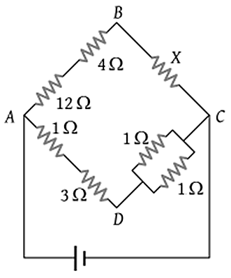
In the circuit shown in the figure below, if the potential difference between \(B\) and \(D\) is zero, then value of the unknown resistance \(X\) is:
| 1. | \(4~\Omega\) | 2. | \(2~\Omega\) |
| 3. | \(3~\Omega\) | 4. | EMF of a cell is required to find the value of \(X\) |
The resistance between terminals \(A\) and \(B\) is:
| 1. | \(5~\Omega\) | 2. | \(15~\Omega\) |
| 3. | \(10~\Omega\) | 4. | \(20~\Omega\) |

| 1. | \(7R\) | 2. | \(5R\) |
| 3. | \(4R\) | 4. | \(3R\) |
A potential divider is used to give outputs of \(2~\text{V}\) and \(3~\text{V}\) from a \(5~\text{V}\) source, as shown in the figure.
| 1. | \({R}_1=1~\text{k} \Omega, {R}_2=1 ~\text{k} \Omega, {R}_3=2 ~\text{k} \Omega\) |
| 2. | \({R}_1=2 ~\text{k} \Omega, {R}_2=1~\text{k} \Omega, {R}_3=2~\text{k} \Omega\) |
| 3. | \({R}_1=1 ~\text{k} \Omega, {R}_2=2~ \text{k} \Omega, {R}_3=2~ \text{k} \Omega\) |
| 4. | \({R}_1=3~\text{k} \Omega, {R}_2=2~\text{k} \Omega, {R}_3=2~ \text{k} \Omega\) |
Twelve wires of equal resistance \(R\) are connected to form a cube. The effective resistance between two diagonal ends \(A\) and \(E\) will be:
| 1. | \(\dfrac{5 R}{6}\) | 2. | \(\dfrac{6 R}{5}\) |
| 3. | \(12 R\) | 4. | \(3 R\) |
The equivalent resistance between \(A\) and \(B\) for the mesh shown in the figure is:
| 1. | \(7.2~\Omega\) | 2. | \(16~\Omega\) |
| 3. | \(30~\Omega\) | 4. | \(4.8~\Omega\) |
The net resistance of the circuit between \(A\) and \(B\) is:
| 1. | \(\dfrac{8}{3}~\Omega\) | 2. | \(\dfrac{14}{3}~\Omega\) |
| 3. | \(\dfrac{16}{3}~\Omega\) | 4. | \(\dfrac{22}{3}~\Omega\) |