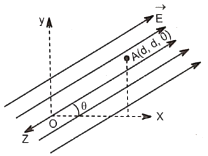
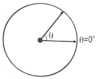
A small electric dipole is placed at the origin with its diploe moment directed along the positive x-axis. The direction of the electric field at a point is
1. along the z-axis
2. along the y-axis
3. along the negative y-axis
4. along the negative z-axis
A uniform electric field of magnitude E and directed along positive x-axis exists in a certain region of space. If at x = 0 the electric potential V is zero, then the potential at is:
1.
2.
3.
4.
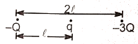
Three charges -Q, q, and -3Q are arranged as shown in the figure. The system of charges will have positive configuration energy if:
1.
2.
3.
4.
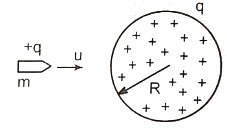
A bullet of mass m and charge q is fired towards a solid uniformly charged sphere of radius R and total charge +q. If it strikes the surface of the sphere with speed u, find the minimum speed u so that it can penetrate through the sphere. (Neglect all resistance force of friction acting on the bullet except electrostatic force.):
1.
2.
3.
4.
1.
2.
3.
4.
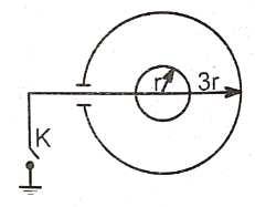
The figure shows two conducting thin concentric shells of radii r and 3r. The outer shell carries charge q and the inner shell is neutral. The amount of charge which flows from the inner shell to the earth after the key K is closed is equal to:
1.
2.
3.
4.
1.
2.
3.
4.
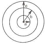
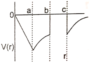
A non-conducting sphere with radius a is concentric with and surrounded by a conducting spherical shell with inner radius b and outer radius c. The inner sphere has a negative charge uniformly distributed throughout its volume, while the spherical shell has no net charge. The potential V(r) as a function of distance from the center is given by:
1. 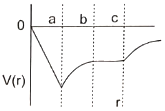 2.
2. 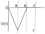
3. 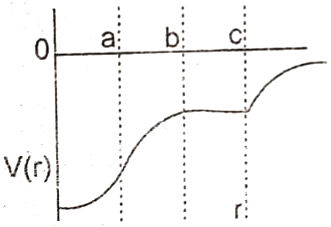 4.
4. 
In the electric field of a point charge q, a certain charge is carried from point A to B, C, D, and E, the work done:
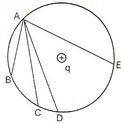
1. is least along the path
2. is least along the path
3. is zero along any one of the path AB, AC, and AE
4. is least along AE.
Charge Q coulombs is uniformly distributed throughout the volume of a solid hemisphere of radius R metres. Then the potential at centre O of the hemisphere in volts is:
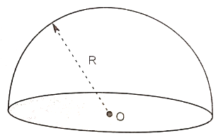
1.
2.
3.
4.
A capacitor of capacitance C is charged to a potential difference V from a cell and then disconnected from it. A charge +Q is now given to its positive plate. The potential difference across the capacitor is now:
1.
2.
3.
4.
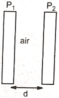
A parallel plate capacitor has two layers of dielectrics as shown in the figure. This capacitor is connected across a battery, then the ratio of potential difference across the dielectric layers is:
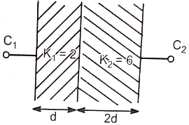
1.
2.
3.
4.
1.
2.
3.
4.
An insulator plate is passed between the plates of a capacitor. Then current(outside the capacitor):
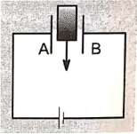
1. Always flows from A to B
2. Always flows from B to A
3. First flows from A to B and then from B to A
4. First flows from B to A and then from A to B
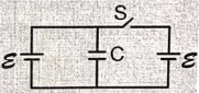
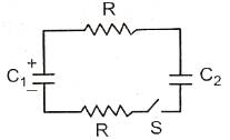
Initially, the circuit is in a steady-state. When the switch S is closed, the heat generated in the circuit will be:
1.
2.
3.
4.
1. 1
2. 1/2
3. 1/9
4. 1/4
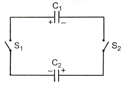
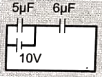
The charge supplied by the battery in the circuit shown in the figure :
1.
2.
3.
4.
1.
2.
3.
4.
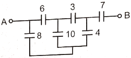
In the circuit diagram shown all the capacitors are in F. The equivalent capacitance between points A and B is. (in )
1. 14/5
2. 7/5
3. 3/7
4. None of these
1. Zero
2.
3. Infinite
4.
